Digital Input and Output
The basic concept of digital input and output is ON/OFF. In digital world, the ON/OFF means 1 and 0.
Everyday you have use a lot of device which driven by digital signal, yeah, it's like remote controller, switch...etc.
So, we will use this concept to understand digital Input and Output(or Digital I/O).
This diagram show the schematic for LED and button.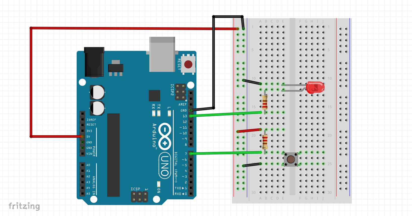 Before we start to understand what the wire connect, we observe the Arduino status.
There are FOUR wires connects to bread board, one red, one black, and two green.
Red wire is POWER.
Black wire is GND.
Green wire is SIGNAL. and, guess what, there means one wire is INPUT SIGNAL, other is OUTPUT SIGNAL.
The basic concept is digital Input and Output. in real world, it's like a switch and a light. when you turn the switch on, the light would be lighting. and now, we will use arduino to implement this flow.
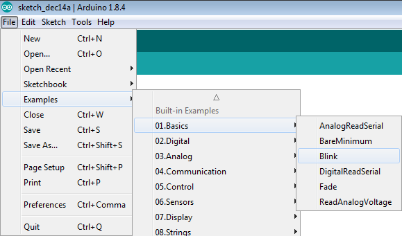
If you want to know where can find the example, don't worry, Arduino IDE provide lot of examples. Open the arduino IDE, please open this example as below picture show.
Arduino IDE will show the example: Blink.ino
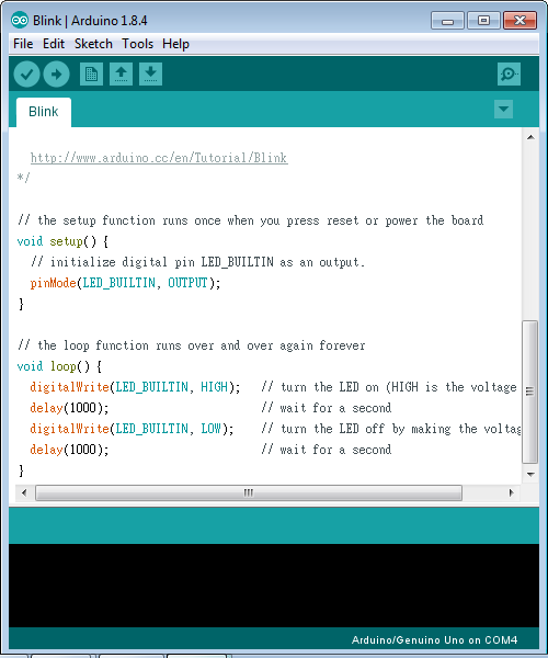
Now, we need to know regarding PROGRAM.
There are two block, one is void setup(){ ... } , another is void loop(){ ...} .
the program in setup() statement will run once between arduino boot up.
the program in loop() statement will run forever when setup had finished.
we usually put the